Description
Why Creepage Distance Matters for PD3 Busbar Insulators
Creepage distance — the shortest path along the surface of an insulating material between two conductive parts — is one of the most critical dimensions engineers evaluate when specifying busbar insulators for switchgear, distribution panelboards, and power electronics cabinets. In environments classified as Pollution Degree 3 (PD3), where conductive pollution, dust, or moisture can accumulate on insulating surfaces, an inadequate creepage path can allow surface tracking to develop between live busbars and grounded backplates, eventually leading to flashover. For panel builders and switchgear OEMs working under IEC 60664-1, correctly calculating creepage distance is inseparable from selecting an insulator material with a proven Comparative Tracking Index (CTI) and a geometry engineered to extend the surface path without increasing overall installation height.
Yueqing City Duwai Electric Co., Ltd., operating under the DOWE Electric brand (also referenced as DUWAI), has spent over two decades engineering insulation solutions for global power distribution infrastructure, with creepage-path design as a core element of its busbar insulator and standoff product lines.
Pollution Degree 3 and the Comparative Tracking Index
Pollution Degree 3 describes operating environments where conductive pollution occurs, or where dry non-conductive pollution becomes conductive due to condensation. In these conditions, the Comparative Tracking Index of the insulating material determines how resistant the surface is to conductive carbon tracking once moisture or dust bridges the creepage path. DOWE’s busbar insulators are manufactured to a CTI of 600V or higher, placing them in Material Group I under IEC 60664-1 — the classification associated with the greatest resistance to tracking and, correspondingly, the ability to use shorter creepage distances for a given working voltage without compromising dielectric safety margins.
Engineering the Creepage Path: Ribbed and Hexagonal Geometries
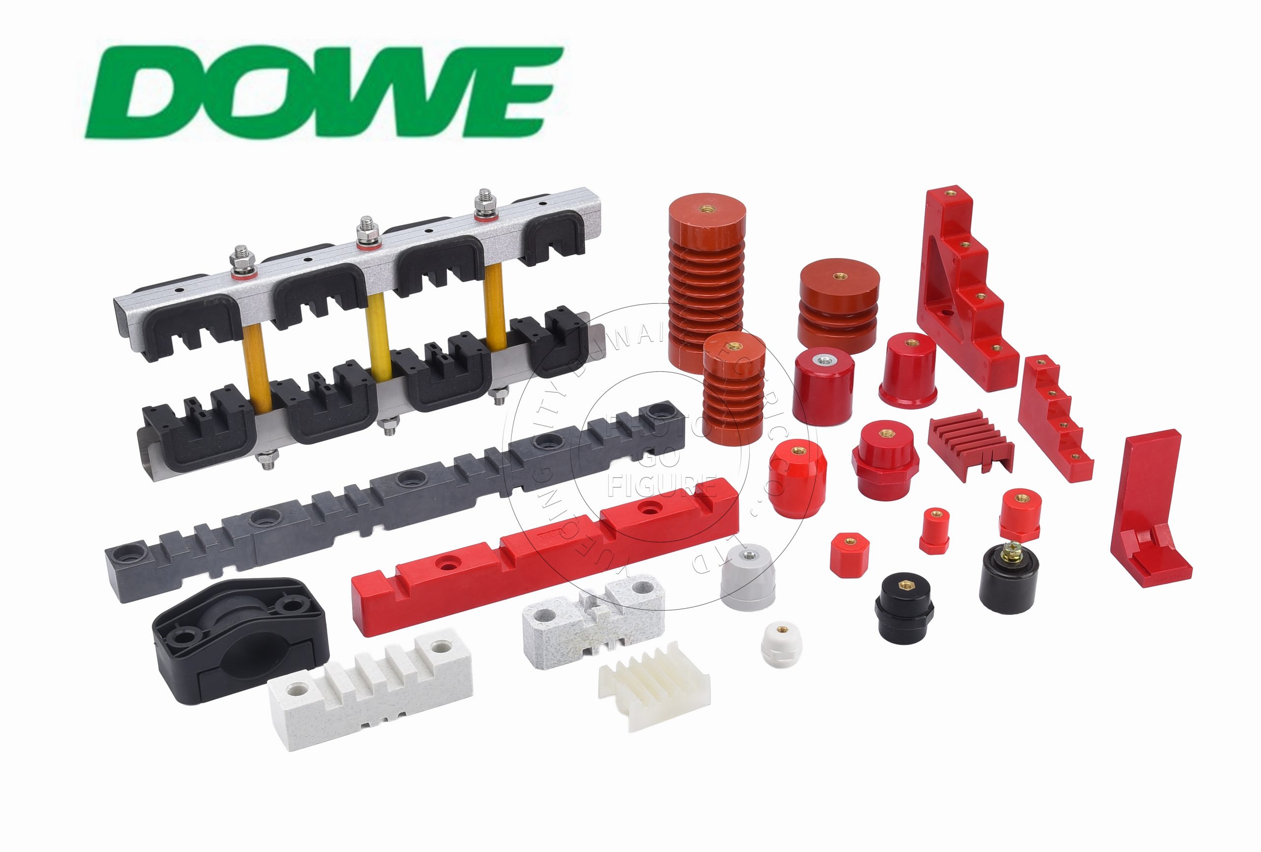
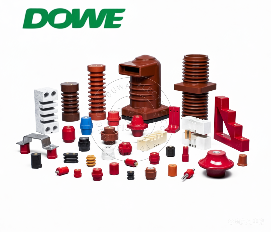
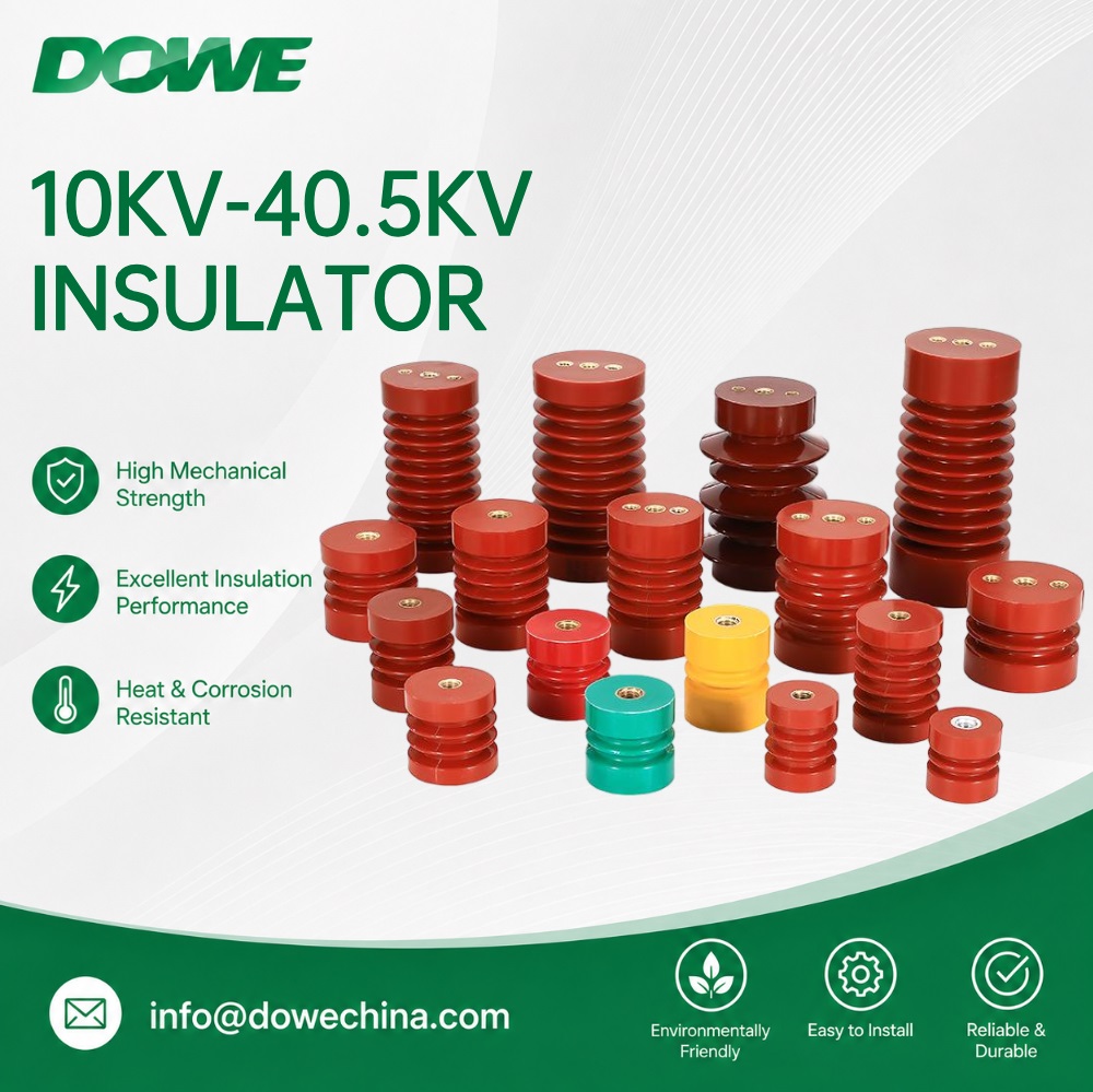
Rather than relying solely on material chemistry, DOWE extends effective creepage distance through geometric design. The SM Series, a conical ribbed standoff insulator built for standard low-voltage switchgear, distribution panelboards, and motor control center cabinets, uses concentric aerodynamic fins that increase the effective surface creepage path by 35% to 60% without increasing vertical installation height. This ribbed profile is specifically engineered for Pollution Degree 3 industrial environments, where a longer surface path is required to prevent tracking between live busbars and grounded chassis backplates.
For high-voltage DC applications up to 1,500V DC — including solar PV, battery energy storage, EV charging, and DC fuse installations — the SB / JYZ Series applies a hexagonal anti-rotation base integrated with a cylindrical upper body. Beyond allowing technicians to apply full tightening torque without rotational shear stress, this family is built from high-grade DMC/BMC/SMC with the same Material Group I CTI of 600V or higher, maintaining thermal endurance from -40°C to +140°C and UL 94-V0 self-extinguishing performance with an afterflame time of no more than 8 seconds and zero flaming drips.
Mechanical and Dielectric Performance Supporting Creepage Calculations
A creepage distance calculation does not stand alone; it is validated against a broader set of dielectric and mechanical metrics. DOWE’s insulation systems are engineered to maintain a Heat Deflection Temperature up to +180°C under 1.8 MPa flexural load and a Relative Thermal Index of 130°C per UL 746B. Coefficient of Thermal Expansion is held between 15 and 22 × 10⁻⁶/K, aligning with copper (16.5 × 10⁻⁶/K) and aluminum (23.1 × 10⁻⁶/K) busbars to limit differential expansion stress during thermal cycling. Low-voltage dielectric withstand is rated at 3,500V AC (50Hz, 1 minute) without puncture or flashover, and surge impulse margin reaches 1.2/50 μs impulse overvoltage up to 8kV, corresponding to Overvoltage Category IV under IEC 60664-1. Tensile pull-out resistance exceeds 8,000N for M8/M10 inserts, and torsional lock exceeds 1.5 times the bolt proof torque — figures that matter because a creepage-optimized insulator must also survive the mechanical stress of short-circuit electrodynamic forces.
Busbar Support Systems and Creepage Spacing in High-Current Switchgear
Creepage and clearance calculations extend beyond standoff insulators into busbar support and clamping systems rated up to 1,100V AC and 6,300A. The EL Series offers pre-molded busbar spacing configurations — EL-130, EL-170, and EL-210 — built in high-strength SMC with longer glass fibers (25mm–50mm) to eliminate manual spacing verification and provide repeatable phase-to-phase distances for 3-pole and 4-pole configurations from 250A to 2,500A. The HC Heavy Duty line extends this to single and multi-pole modular configurations up to 6,300A with a short-circuit withstand (Icw) of up to 100kA/1s for utility substations. The XD3-D4 Series accommodates variable busbar bar-counts of one to three bars per phase through a modular interlocking design, while the Single / Three Phase clamp line serves branch take-off and phase-splitting applications from 100A to 1,250A in BMC/DMC construction.
Medium-Voltage Creepage Engineering: DW and EL MV Series
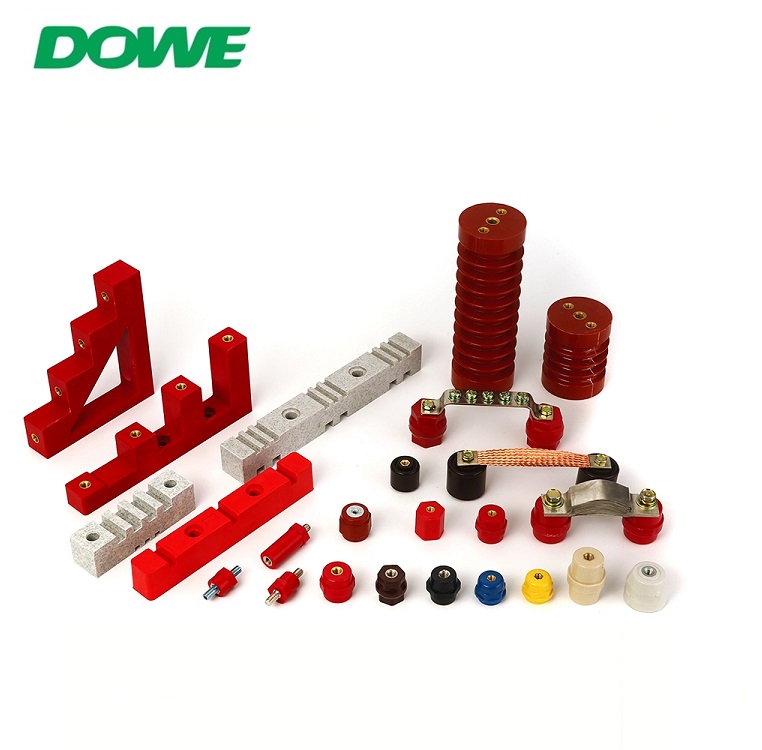
For medium-voltage ranges of 3.6 kV to 12 kV AC, creepage path design becomes even more demanding. The DW Series post insulator uses a DMC/BMC/SMC composite across install heights of 30mm to 130mm to deliver elevated creepage performance for clean indoor switchgear and secondary distribution substations. For harsher, humid, and dusty industrial environments, ring main units, and VFD drive cabinets, the EL MV Series relies on vacuum-cast epoxy resin (hot-curing bisphenol-A, automated pressure gelation) across install heights of 130mm to 360mm for 3.6 kV to 7.2 kV AC. Its hydrophobic surface prevents moisture film continuity, volume resistivity exceeds 10¹⁴ Ω·cm, void-free monolithic casting limits partial discharge to less than 5 pC at 1.1 Um, and dielectric loss angle tan δ remains no greater than 0.005 at 20°C.
Certifications Validating Creepage and Dielectric Performance
DOWE’s creepage and dielectric engineering is documented against IEC 61439-1/2, IEC 60664-1, IEC 60273, IEC 60071, and IEC 60815, alongside UL 94-V0 flammability certification, RoHS (2011/65/EU & 2015/863) and REACH (EC 1907/2006) compliance, CE clearance, UL 746B Relative Thermal Index certification, and SGS third-party type test clearance. Panel builders can reference these SGS reports to complete Design Verification documentation without conducting independent destructive testing.
Industry Applications
These creepage-engineered insulators and busbar supports serve solar PV inverter DC links, BESS storage cabinets, lithium battery pack interconnects, EV and fast-charging infrastructure, DC fuse and disconnector mounting bases, low-voltage switchgear and panelboards, railway trackside power, mining power boxes, utility substations, ring main units, and VFD cabinets — markets DOWE serves across more than 60 countries in Europe, the Americas, the Middle East, Southeast Asia, and Australia.
Conclusion
Accurately calculating creepage distance for Pollution Degree 3 conditions requires more than a formula — it requires validated materials, proven geometry, and certified test data. DOWE Electric, the export brand of Yueqing City Duwai Electric Co., Ltd., brings all three together through its ribbed and hexagonal insulator geometries, Material Group I CTI 600V formulations, and certified busbar support systems built for the dielectric, thermal, and mechanical demands of modern power distribution infrastructure.


Reviews
There are no reviews yet.